> Important notice! : There's currently 10 days of delay between your order and shipment for all pedals.> USA : I ship with Delivery Duty Paid. That means 15% tariff for European goods will be added at check out and you will have no further custom fees.
This website uses cookies to manage authentication, navigation, and other functions. By using our website, you agree that we can place these types of cookies on your device.
You have declined cookies. This decision can be reversed.
TremolOo_oOo_oOo_oOo_oOo!!!
Details
Introduction
I’ve been working on a tremolo for a few days, and thought it could be interesting to discuss this simple effect, yet not that easy to build. If you’re a DIYer building a tremolo, I hope this document can provide some inspiration, «Do’s and don’t » and useful links. Also, for the future and current Zorglonde tremolo users, this will unveil some of its mysteries and help for a better use of it.
A tremolo does a simple thing: it just changes automatically your signal's volume. Your volume goes up and down, according to a periodical waveform. But the feeling you’ll get will be different according to the rate (or frequency), the depth and the shape of that waveform. You can listen to different settings of waveform, rate and depth of a tremolo on this Zorglonde first test recording:
The plan for this LONG paper, is first to give my requirements and design choices, then we’ll discuss all available possibilities to design a tremolo and in the end we’ll see the problems I encountered with the choices I made and how I solved them.
I should add that this article is complementary of Coda Effects paper on his tremolo :
http://www.coda-effects.com/2016/05/tap-tempo-tremolo-diy-complex-project.html
This article is interesting in the fact that Coda described a philosophy quite at the opposite of the one I chose…
My requirements and choices:
When Dorian from Høst asked if I could build him a tremolo, I thought it would be an interesting yet simple and fast work. And I was wrong. Setting up a good oscillators took me one full week of research…
But first I gave myself the following constraints :
It should fit in a small 6x11cm enclosure.
Tremolo rate should be controlled by an expression pedal.
Tremolo rate should range from 1Hz to 15Hz.
LFO choices between sine and square waveforms.
The second thing I had to do, given these constraints, was to choose amongst all the technicals possibilities I have to build such a pedal. Some may know that I’m bored with “transparent devices” and I’m most of the time whiling to go to the solution that will add a little (or big) something to the sound. So my choices where mostly inspired by this white paper from Strymon :
http://www.strymon.net/amplifier-tremolo-technology-white-paper/
And so at the beginning, I chose to go for a JFET bias and a phase shift oscillator. This is a classic vintage tremolo design, so it would fit my colourful sound wish. We’ll see in the next chapters what kind of choices they are and that I had to change my plans a little bit to fulfil all my requirements...
Discussing technologies :
So if you consider the electronics of a tremolo, you can breakdown the design in two:An automatic volume control, to move the signal volume up and down and a low frequency oscillator, which will create a periodical signal that will control the automatic volume control part.
For the automatic volume control we can use these technologies:
DSP volume control.
Transconductance amplifiers volume control.
Optical volume control.
JFET used as a variable resistance volume control.
This one feels kind of a canon to kill a bee… That’s what Strymon does in the Flint. It’s a pertinent choice if you’re a DSP guru, and if you plan to generate complex tremolo LFO waveforms with a DSP, or if you want to have presets and tap tempo. Good also if you plan to use your DSP platform for others projects later. But starting from scratch, it’ll be a lot of work!
Transconductance amplifiers volume control.
This seems to me like a perfect device to achieve a tremolo. Using for example a LM13700 would provide low distortion, clean and accurate tremolo. Also it will still respond very well to oscillators into the audio frequency range (from 20Hz to 20kHz), given the right oscillator you may use also your tremolo as a ring modulator (AM modulation) !
But this was too clean for me…
Figure 1: Typical LM13700 use for automatic volume control
Optical volume control.
The optical volume control can be made using a photo-resistance such as a VTL5Cx or NSL-32. They can be used either in a tension divider or by controlling an opamp gain:
Figure 2: Simple tension divider
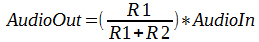
Illustration 2 shows a simple tension divider which will give:
So if R1=0 there’s no audio out, and if R1 is infinite, R2 is negligible and Audio Out= Audio In.
The following schematic shows a NSL-32 optocoupler used to automatically control Audio Out:
Figure 3: NSL32 controlled tension divider
Given the NSL-32 datasheet: When its led is fully on, Ron = 500Ω, and when the led is fully off Roff=500kΩ, so we see that if we take R2 = 10kΩ we’ll get:
When the NSL-32 led is on: Audio Out = 0.047 x Audio In
When the NSL-32 led is off: Audio Out = 0.98 x Audio In
And we can see that achieving a perfect 0V output won’t be possible…
Now if we use an opamp:
Figure 4: NSL-32 Controlling opamp gain
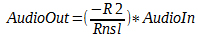
In this case the opamp gain is given by:
If we take R1 = 500Ω we’ll get:
When the NSL-32 led is on: Audio Out = - Audio In
When the NSL-32 led is off: Audio Out = - 0.001 x Audio In
Which is a bit better! Even if you will get better results with a VTL5C3 who gives the following values: Ron=1,5Ω, Roff=10MΩ...
But in the end, for me these devices have tons of drawbacks :
They’re are expensive ! (up to 10€ for VTLs)
They’re not ROHS compliant.
You have to select them, specially NSL-32 which have very different response curves…
They’re not very linear in response…
They’re slow. Forget about the ring modulation with these. Square waveforms will also be filtered a bit by these devices, but nothing dramatic though.
The only advantage is that they’re easy to use and it simplifies you design a LOT !
But if you’re only into square waveform tremolo you might also consider BJT optocouplers. This is a led driving a transistor. But this is something I did not focused on, so I won't develop it here.
JFET used as a variable resistance volume control.
The JFET used as a variable resistance can be used in the same way as optical volume control : either a tension divider or controlling an opamp gain:
Figure 5: FET transistor in a tension dividerFigure 6: FET transistor in an inverting AOP
If we use a J107 jFET, the same calculations as upper applies here, but with Rds on = 8Ω (Vgs = 0V) and Rds Off > 2MΩ (with Vgs > -2,5V), it’s actually better than with NSLs and similar as VTLs but 15-20 times cheaper!
(Note that jFETs values are subject to very large tolerances and these values are subject to changes, but still they’re very good!)
On some points they’re better that optical devices : they’re cheap, fast, smaller, Rohs compliant and you may or may not select them…
But they also have drawbacks :
For a J107, the instrument signal on the drain must not be higher than 2Vcc or it will make the jFET clip. And some very high output humbuckers can generate signals of 2Vcc…
On a n-fet you’ll need to apply a negative tension between the grid and the source to make it work as a variable resistance.
They’re also not linear.
Figure 7: FET resistor distortion on a 1Vcc 400Hz sin waveform
Transistor bias volume control.
This also works with a tube. But if you make the bias of a FET preamp change by changing its source's voltage, it’ll change the gain of your preamp. The advantage of this method is that it’s fast, linear and cheap. The disadvantage is that at low gain, distortion will occur. And that’s this distortion I was thinking when saying I wanted a colourful tremolo ! Because the cool thing is that the more your volume goes down because of the LFO, the more distortion occurs… So as it happens during low volume phase of the tremolo, there’s a little psychoacoustic something happening in your brain. That’s where the magic comes from!
It has also another disadvantage: it won’t work well with square waveforms. But this will be discussed later.
Figure 8: FET bias schematic.
The illustration below shows the distortion occurring on a 200Hz sine waveform when a 4Hz LFO of 4Vcc is applied to the FET source. As you can see it’s pretty nasty (YAY!!!):
Figure 9: Distortion caused by jFET bias changes with the LFO
Let’s talk about LFO’s...
Doing a square waveform LFO is easy and there’s plenty of designs possibilities for a good square LFO with a huge range like from 1Hz to 1Mhz... Same for a triangle waveform LFO or a Sawtooth, which are a bit trickier than square, but still easy.
On the contrary doing a good sine LFO over a wide frequency range can be a nightmare. A good sine LFO have the ability to generate a perfect sine waveform over a large frequency range. And in terms of sine, « large » can range from from 1Hz to 15Hz!
Digital LFO.
There are various way’s to create a digital LFO, either with a DSP, or with filtered PWM’s on a 8/16 bits microcontroller, or with filtered discrete IC’s counters… It’s the only way I know to get a very large range of frequencies available with the less distortion. Also it allows to do all kind of waveform with no limits: sine, triangle, square, sawtooth, random, half sines, step sine, etc. Check Coda Effects paper mentioned above it’s got a few examples.
It’s also the only way to achieve tap tempo control of the waveform.
My main concern about that was it might take too much space on the board, even if a small ATtiny could do the trick with a PWM filtered LFO...
Also developing code from scratch for such a LFO would take a lot of time, even if tutorials can be found all over the Internet to reduce coding time.
And last but not least, you can find already programmed ICs for a faire price, at Electric Druid for example :
http://electricdruid.net/product/taplfo-tap-tempo-lfo/
Dedicated integrated circuits.
I’m talking about ICs like Maxim’s MAX038 or Exar’s XR2206. These circuits are a bit expensive (God the MAX038 costs 25€!!!), but are simple to use, gives low distortion waveforms over a very wide range (From 2Hz to 4kHz for the XR and 2Hz to 700Hz for the MAX).
Check them datasheets for an overview of what they can do :
https://www.sparkfun.com/datasheets/Kits/XR2206_104_020808.pdf
But they were just too expensive for me and easily dismissed by Electric Druid LFO’s in my opinion…
Wien bridge.
When it comes to analog sine waveform oscillators, it’s the first idea that comes to the mind. You can get a great sine waveform out of it until you want to sweep it’s frequency. The Wien bridge is simple to understand and uses few components:
Figure 10: Base schematic of a wien bridge oscillator.
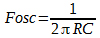
With the schematic above, if you want oscillation to happen, you’ll need R1=R2=R, C1=C2=C and R3>R4.
Then the oscillation frequency will be:
There’s a fine explanation on how it works on Wikipedia:
https://en.wikipedia.org/wiki/Wien_bridge_oscillator
The most important part of it being: “The oscillator can be viewed as a positive gain amplifier combined with a bandpass filter that provides positive feedback. […] In practice, the loop gain is initially larger than unity. Random noise is present in all circuits, and some of that noise will be near the desired frequency. A loop gain greater than one allows the amplitude of frequency to increase exponentially each time around the loop. With a loop gain greater than one, the oscillator will start.
Ideally, the loop gain needs to be just a little bigger than one, but in practice, it is often significantly greater than one. A larger loop gain makes the oscillator start quickly. A large loop gain also compensates for gain variations with temperature and the desired frequency of a tunable oscillator. For the oscillator to start, the loop gain must be greater than one under all possible conditions.
A loop gain greater than one has a down side. In theory, the oscillator amplitude will increase without limit. In practice, the amplitude will increase until the output runs into some limiting factor such as the power supply voltage (the amplifier output runs into the supply rails) or the amplifier output current limits. The limiting reduces the effective gain of the amplifier (the effect is called gain compression). In a stable oscillator, the average loop gain will be one.”
So, you can actually change the frequency of the Wien bridge a little by using a single pot on R1. But for a larger range, you’ll need to control both R1 and R2 with a dual pot. And even then it’ll rapidly go into distortion in one end, or attenuation in the other end. A x4 range (2Hz to 8Hz) is the best thing you might achieve with a doubled ganged pot and that with lots of distortion and amplitude issues.
Some suggest to use a special lightbulb instead of R3 to enhance the stability, or to use a double ganged variable capacitor for C1 and C2. Well if you’re lucky enough to have one of these exotic devices you may give a go.
But more importantly, you can enhance the Wien bridge design with an automatic gain control to achieve a better range. I didn’t had the will and the time to test it but it might be worth a test:
Figure 11: Wien bridge with automatic gain control
But in the end the Wien bridge was discarded by the expression pedal requirement : there’s no double ganged pot in an expression pedal.
Phase shift LFO.
The phase shifter LFO is a classic design that is used in many tremolos, specially into vintage tube amp tremolos. The cool thing about this design is that it’s done with very few cheap components, it can work with either a transistor or an AOP, though it’s understanding can be a bit complex:
Figure 12: Phase shifter with AOPFigure 13: Phase shifter with bipolar transistor.
In the case of the transistor version, a way to understand it simply is that if the transistor is closed, current will flow into the RC cells, in which it’ll be delayed, until it reaches the transistor base. As the RC cells charges slowly the base will slowly open the transistor and the current will slowly fade out in the RC cells causing them to discharge. And while discharging the transistor will close itself, and current will again flow through the cells and etc.
There’s a need to have a gain of 30 either with the opamp (R4= 30xR) or the transistor. With the transistor you’ll need to buffer the output if you want to attack a low impedance device with its output.
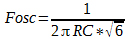
You can also add more RC cells to improve frequency stability and distortion. But if you get R1=R2=R3=R and C1=C2=C3=C, the 3 RC cell version will oscillate at:
But this design has also the same drawback as the Wien Bridge: range is very limited and there’s a good amount of distortion. But still you can achieve a x4 range with a simple standard pot, dual ganged pots would let you achieve a x5 or x6 range and you get even more with a triple ganged pot. But still it has a lot of distortion and the sin waveform is far from being perfect.
Check out this page for more informations, it also show at the end how distorted the output is:
http://home.earthlink.net/~doncox/wec/Oscillators.html
I thought this design would be good enough and I spent a lot of time tweaking it, trying to match my requirements. Which revealed to be impossible, the range was always too small!
Also far better results can be achieved with a buffered or a Bubba design, but it will use more components and space. Check them out on this page:
http://sound.whsites.net/articles/sinewave.htm
Quadrature oscillator.
you’ll need a triple ganged pot for this one... So let's discard it rapidly...
Band pass filter oscillator.
This was my final choice. It’s a simple design, with few cheap components. It uses a simple mono pot which meets the requirements. The sine waveform generated has very low distortion and the range is nice for a tremolo, like x15. My design can go from 1Hz to 16Hz, but there’s a bit of signal loss in the high end (16Hz sine amplitude is half of the 8Hz sine). And anything below 1Hz is just too slow for a tremolo.
Figure 14: Final band pass oscillator
The above schematic shows the final design with components values to achieve a 1Hz to 16Hz range and expression pedal (10k pot) implementation between exp_ring and exp_tip.
It’s as simple as the Wien bridge: the right AOP is a bandpass filter which central frequency is trimmed by the RATE pot. The AOP provides unity feedback to maintain the central frequency oscillation. Diodes D3 and D4 are used to limit the oscillation amplitude to 2Vcc.
Just remember that if this design works great as a LFO, it seems not to be a very good sine waveform generator in the audio range or above if a large range is needed.
Designing the Zorglonde.
So the design choices made were : Band pass filter LFO and JFET bias.
To get a square waveform LFO I simply used a saturated transistor to get the square waveform from the sine waveform. The square waveform is not perfect but it’ll do. You can add another saturated transistor to make it better if you need. Bonus, putting the led on the transistor collector will give you a led blinking at the LFO frequency:
Figure 15: Sine to square design
But then came the first issue with the bias design: When the LFO is about the top end (12Hz, 16Hz), and the more your LFO is distorted, the more low frequency noise you’ll ear. This is normal, as the bias of the FET is changed by the LFO, the LFO frequency is directly introduced in the FET’s drain output:
Figure 16: Fet bias drain output at 15Hz: Red is the LFO output, Blue is the modulated input sound where the LFO is present.
So you’ll first need a heavy filtering on low frequency to minimize this noise. But if the sine LFO have some distortion it will be difficult to remove remaining higher harmonics that will pop up in the audio range. In my case 3 high pass RC cells cutting around 80Hz have been added. It’s giving the following result:
Figure 17: Fet bias drain output at 15Hz: Red is the LFO output, Blue is the modulated output sound. Still not perfect, but quite better!Figure 18: et bias drain output at 8Hz: Red is the LFO output, Blue is the modulated output sound. Quite perfect at this frequency!
But this problem gets worse when you switch to square LFO, as it introduce some high frequency glitches when changing from low to high state, and this even at low (like 2Hz) frequencies. And these ticks can’t be removed, or you’ll remove all you guitar sound trying to remove it!
So the JFET bias, is BAD with a square waveform! In order to use the square waveform LFO, I used a JFET as a variable resistance, building a tension divider before the jFET :
Figure19: Final automatic volume control design with square and sine waveform controls
In this design, the values of the tension divider where chosen to minimize clipping in the variable resistance FET, and try to reduce the most powerful humbucker signal below 2Vcc. An interesting thing being if you change the resistance values with the switch, you can adapt the tremolo to your pickups, and gain some headroom if you have vintage single coils, or get some badass grit if you have high output pickups. The tension divider values were also chosen to minimize glitch noise. With this design glitches from the square waveform are highly diminished, but if resistance values are too high you’ll still ear it a tiny bit if your tremolo is before a high gain distortion.
Then I had to keep the sine waveform LFO used as a bias volume control, cause if you wonder what happens if you route the sine LFO to the jFET used in the tension divider, here’s what you get: awful linearity.
Figure 20: 400Hz sine shaped badly by a FET in a tension divider with a 6Hz sine LFO
Drawback of this design is that I had to use a charge pump circuit to create -9v out of the 9v power input. The oscillator won’t work with 0-9v, and I needed a negative tension on the FET as a variable resistance grid.
Conclusion.
As a conclusion, let's just stare at the output of this tremolo. Depth setting is the same for all curves, except the pulse curve where it's a bit deeper.
For the sine waveform.
400Hz sine modulated by a 1Hz sine400Hz sine modulated by a 7-and something-Hz sine400Hz sine modulated by a 14Hz sine400Hz sine modulated by a 1Hz sine. By turning the depth a little further you get these nice pulses.
For the square waveform.
400Hz sine modulated by a 1Hz square400Hz sine modulated by a 7-and something-Hz square400Hz sine modulated by a 14Hz square


 So if R1=0 there’s no audio out, and if R1 is infinite, R2 is negligible and Audio Out= Audio In.
The following schematic shows a NSL-32 optocoupler used to automatically control Audio Out:
So if R1=0 there’s no audio out, and if R1 is infinite, R2 is negligible and Audio Out= Audio In.
The following schematic shows a NSL-32 optocoupler used to automatically control Audio Out:


 If we take R1 = 500Ω we’ll get:
When the NSL-32 led is on: Audio Out = - Audio In
When the NSL-32 led is off: Audio Out = - 0.001 x Audio In
Which is a bit better! Even if you will get better results with a VTL5C3 who gives the following values: Ron=1,5Ω, Roff=10MΩ...
But in the end, for me these devices have tons of drawbacks :
If we take R1 = 500Ω we’ll get:
When the NSL-32 led is on: Audio Out = - Audio In
When the NSL-32 led is off: Audio Out = - 0.001 x Audio In
Which is a bit better! Even if you will get better results with a VTL5C3 who gives the following values: Ron=1,5Ω, Roff=10MΩ...
But in the end, for me these devices have tons of drawbacks :


 There’s a fine explanation on how it works on Wikipedia:
https://en.wikipedia.org/wiki/Wien_bridge_oscillator
The most important part of it being: “The oscillator can be viewed as a positive gain amplifier combined with a bandpass filter that provides positive feedback. […] In practice, the loop gain is initially larger than unity. Random noise is present in all circuits, and some of that noise will be near the desired frequency. A loop gain greater than one allows the amplitude of frequency to increase exponentially each time around the loop. With a loop gain greater than one, the oscillator will start.
Ideally, the loop gain needs to be just a little bigger than one, but in practice, it is often significantly greater than one. A larger loop gain makes the oscillator start quickly. A large loop gain also compensates for gain variations with temperature and the desired frequency of a tunable oscillator. For the oscillator to start, the loop gain must be greater than one under all possible conditions.
A loop gain greater than one has a down side. In theory, the oscillator amplitude will increase without limit. In practice, the amplitude will increase until the output runs into some limiting factor such as the power supply voltage (the amplifier output runs into the supply rails) or the amplifier output current limits. The limiting reduces the effective gain of the amplifier (the effect is called gain compression). In a stable oscillator, the average loop gain will be one.”
So, you can actually change the frequency of the Wien bridge a little by using a single pot on R1. But for a larger range, you’ll need to control both R1 and R2 with a dual pot. And even then it’ll rapidly go into distortion in one end, or attenuation in the other end. A x4 range (2Hz to 8Hz) is the best thing you might achieve with a doubled ganged pot and that with lots of distortion and amplitude issues.
Some suggest to use a special lightbulb instead of R3 to enhance the stability, or to use a double ganged variable capacitor for C1 and C2. Well if you’re lucky enough to have one of these exotic devices you may give a go.
But more importantly, you can enhance the Wien bridge design with an automatic gain control to achieve a better range. I didn’t had the will and the time to test it but it might be worth a test:
There’s a fine explanation on how it works on Wikipedia:
https://en.wikipedia.org/wiki/Wien_bridge_oscillator
The most important part of it being: “The oscillator can be viewed as a positive gain amplifier combined with a bandpass filter that provides positive feedback. […] In practice, the loop gain is initially larger than unity. Random noise is present in all circuits, and some of that noise will be near the desired frequency. A loop gain greater than one allows the amplitude of frequency to increase exponentially each time around the loop. With a loop gain greater than one, the oscillator will start.
Ideally, the loop gain needs to be just a little bigger than one, but in practice, it is often significantly greater than one. A larger loop gain makes the oscillator start quickly. A large loop gain also compensates for gain variations with temperature and the desired frequency of a tunable oscillator. For the oscillator to start, the loop gain must be greater than one under all possible conditions.
A loop gain greater than one has a down side. In theory, the oscillator amplitude will increase without limit. In practice, the amplitude will increase until the output runs into some limiting factor such as the power supply voltage (the amplifier output runs into the supply rails) or the amplifier output current limits. The limiting reduces the effective gain of the amplifier (the effect is called gain compression). In a stable oscillator, the average loop gain will be one.”
So, you can actually change the frequency of the Wien bridge a little by using a single pot on R1. But for a larger range, you’ll need to control both R1 and R2 with a dual pot. And even then it’ll rapidly go into distortion in one end, or attenuation in the other end. A x4 range (2Hz to 8Hz) is the best thing you might achieve with a doubled ganged pot and that with lots of distortion and amplitude issues.
Some suggest to use a special lightbulb instead of R3 to enhance the stability, or to use a double ganged variable capacitor for C1 and C2. Well if you’re lucky enough to have one of these exotic devices you may give a go.
But more importantly, you can enhance the Wien bridge design with an automatic gain control to achieve a better range. I didn’t had the will and the time to test it but it might be worth a test:


 But this design has also the same drawback as the Wien Bridge: range is very limited and there’s a good amount of distortion. But still you can achieve a x4 range with a simple standard pot, dual ganged pots would let you achieve a x5 or x6 range and you get even more with a triple ganged pot. But still it has a lot of distortion and the sin waveform is far from being perfect.
Check out this page for more informations, it also show at the end how distorted the output is:
http://home.earthlink.net/~doncox/wec/Oscillators.html
I thought this design would be good enough and I spent a lot of time tweaking it, trying to match my requirements. Which revealed to be impossible, the range was always too small!
Also far better results can be achieved with a buffered or a Bubba design, but it will use more components and space. Check them out on this page:
http://sound.whsites.net/articles/sinewave.htm
But this design has also the same drawback as the Wien Bridge: range is very limited and there’s a good amount of distortion. But still you can achieve a x4 range with a simple standard pot, dual ganged pots would let you achieve a x5 or x6 range and you get even more with a triple ganged pot. But still it has a lot of distortion and the sin waveform is far from being perfect.
Check out this page for more informations, it also show at the end how distorted the output is:
http://home.earthlink.net/~doncox/wec/Oscillators.html
I thought this design would be good enough and I spent a lot of time tweaking it, trying to match my requirements. Which revealed to be impossible, the range was always too small!
Also far better results can be achieved with a buffered or a Bubba design, but it will use more components and space. Check them out on this page:
http://sound.whsites.net/articles/sinewave.htm